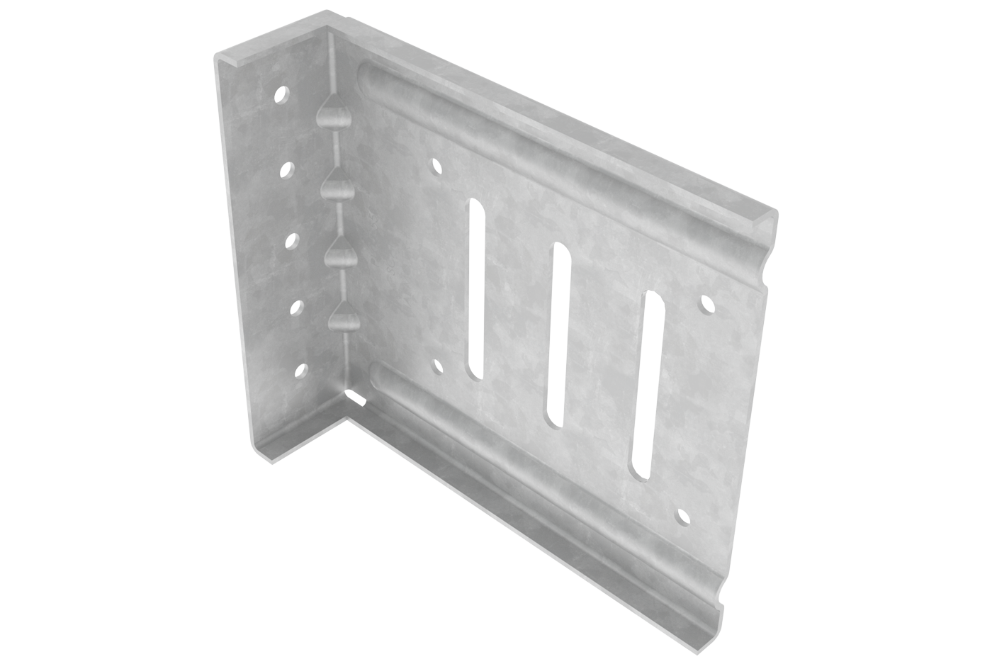
The PLC4 Bypass Clip is a premium option for bypass curtain wall connections. The PLC4’s advanced design provides secure attachment to the main building structure while allowing seamless vertical deflection. The bypass clip has multiple features specifically designed to improve the user experience.
Features & Benefits
The PLC4 Bypass Clip has been engineered to provide the greatest allowable loads in the industry. The clip was designed with contractor input to be user-friendly and save labor. The following features help make this product the leader in the industry.
Premium Product
- Quicker installation (custom screws)
- Safer material handling (chamfered corners)
- Increased load capacity
Download PLC4 Brochure
Material Composition
Clip Composition
- 68 mil (14 ga.) steel thickness
- 57 ksi yield strength
- 65 ksi tensile strength
- G90 galvanized coating
- ASTM A653/A653M
Custom Screw Composition
- ASTM C1513
- C 1022 case hardened steel
- Zinc plated coating
- 1000 hours salt spray life
- Exceeds standard screw life by over 10X
Allowable Loads
| Part No. | Stud Thickness | F1 Allowable Loads (lbs) 2 #14 Screws | ||||
|---|---|---|---|---|---|---|
| Mils | Gauge | Fy (ksi) | Tension (lbs) | Compression (lbs) | ||
| PLC4 350 |
||||||
| 33EQS | 20 | 57 | 485 | 510 | ||
| 33 | 20 | 33 | 485 | 510 | ||
| 43EQS | 18 | 57 | 601 | 621 | ||
| 43 | 18 | 33 | 601 | 621 | ||
| 54 | 16 | 50 | 928 | 935 | ||
| 68 | 14 | 50 | 1242 | 1086 | ||
| 97 | 12 | 50 | 1242 | 1086 | ||
| 118 | 10 | 50 | 1242 | 1086 | ||
| Maximum Allowable Clip Load | 1242 | 1086 | ||||
| Part No. | Stud Thickness | F1 Allowable Loads (lbs) 2 #14 Screws | F1 Allowable Loads (lbs) 3 #14 Screws | ||||
|---|---|---|---|---|---|---|---|
| Mils | Gauge | Fy (ksi) | Tension | Compression | Tension | Compression | |
| PLC4 550 750 950 |
|||||||
| 33EQS | 20 | 57 | 485 | 510 | 738 | 784 | |
| 33 | 20 | 33 | 485 | 510 | 738 | 784 | |
| 43EQS | 18 | 57 | 601 | 621 | 950 | 1006 | |
| 43 | 18 | 33 | 601 | 621 | 950 | 1006 | |
| 54 | 16 | 50 | 928 | 935 | 1367 | 1411 | |
| 68 | 14 | 50 | 1242 | 1086 | 1480 | 1986 | |
| 97 | 12 | 50 | 1242 | 1086 | 1480 | 1936 | |
| 118 | 10 | 50 | 1242 | 1086 | 1480 | 1936 | |
| Maximum Allowable Clip Load | 1242 | 1086 | 1480 | 1936 | |||
Table Notes
- Steel-Con proprietary #14 shouldered screws described in section 3.2.2 of IAPMO ER 0494 must be used for allowable loads.
- Allowable loads are minimum of: ASD Allowable loads from testing, and 1/8” relative deflection service limit.
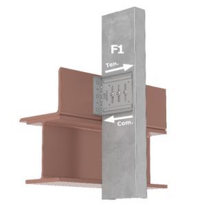
- Reference figure to the right for F1 Load direction and definition.
- Number of screws shall be designated by design professional to meet loading conditions.
Quantity / Order Information
| Part No. | Width | Qty / Bucket | Lbs / Bucket |
|---|---|---|---|
| PLC4-350 | 3 ½” | 35 | 19 |
| PLC4-550 | 5 ½” | 35 | 26 |
| PLC4-750 | 7 ½” | 35 | 34 |
| PLC4-950 | 9 ½” | 25 | 30 |
All PLC4 clips include shouldered screws. Additional lengths available upon request.