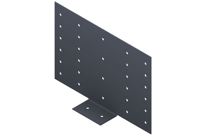
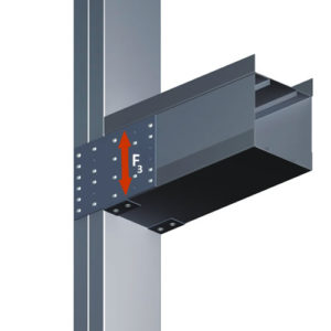
Steel-Con’s secure plate header gusset (HG) is designed to provide a stiffened attachment of two individual members. Its unique design transfers the vertical load through a rigid connection that is far superior than traditional methods of construction.
The header gusset contributes to the headers web crippling and shear capacity, allowing the header to withstand larger loads and decrease the chance of possible failure from job site connections.
Features
- Replaces traditional labor intensive installation methods
- Pre-punched guide holes for quick attachment
- Ledger tabs to hold header during installation
- Designed for multiple stud sizes and jamb configurations
HG Submittal Download
Material Composition
- ASTM A653/A653M
- 43 mil: yield strength: 33 ksi
- 68 mil: yield strength: 57 ksi
- 43 mil: G60 hot dipped galvanized coating
- 68 mil: G90 hot dipped galvanized coating
- Material thickness = 43 mil
- Material thickness = 68 mil
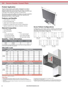
Allowable Loads
All screw pattern configurations depicted with jamb stud located on left hand side of clip.
| Part No. | Stud Properties | F3 Allowable Loads (lbs) | |||||||
| Mil | Gauge | Fy (ksi) | 4 #10 Screws | 6 #10 Screws | 8 #10 Screws | 10 #10 Screws | 12 #10 Screws | ||
| HG -43 (43 mil) |
33EQS | 20 | 57 | 804 | 1206 | 1608 | 2010 | 2412 | |
| 33 | 20 | 33 | 707 | 1060 | 1414 | 1767 | 2120 | ||
| 43EQS | 18 | 57 | 1269 | 1904 | 2538 | 2980 | 2980 | ||
| 43 | 18 | 33 | 1052 | 1578 | 2104 | 2630 | 2980 | ||
| 54 | 16 | 50 | 1388 | 2082 | 2776 | 2980 | 2980 | ||
| 68 | 14 | 50 | 1388 | 2082 | 2776 | 2980 | 2980 | ||
| 97 | 12 | 50 | 1388 | 2082 | 2776 | 2980 | 2980 | ||
| 118 | 10 | 50 | 1388 | 2082 | 2776 | 2980 | 2980 | ||
| Maximum Allowable Clip Capacity | Max F3 = 2980 lbs | ||||||||
| Part No. | Stud Properties | F3 Allowable Loads (lbs) | ||||||
| Mil | Gauge | Fy (ksi) | 4 #10 Screws | 6 #10 Screws | 8 #10 Screws | 10 #10 Screws | 12 #10 Screws | |
| HG-68 (68 mil) |
33EQS | 20 | 57 | 804 | 1206 | 1608 | 2010 | 2412 |
| 33 | 20 | 33 | 707 | 1060 | 1414 | 1767 | 2120 | |
| 43EQS | 18 | 57 | 1269 | 1904 | 2538 | 3173 | 3808 | |
| 43 | 18 | 33 | 1052 | 1578 | 2104 | 2630 | 3156 | |
| 54 | 16 | 50 | 2136 | 3205 | 4273 | 5341 | 5375 | |
| 68 | 14 | 50 | 3021 | 4531 | 5375 | 5375 | 5375 | |
| 97 | 12 | 50 | 3170 | 4755 | 5375 | 5375 | 5375 | |
| 118 | 10 | 50 | 3170 | 4755 | 5375 | 5375 | 5375 | |
| Maximum Allowable Clip Capacity | Max F3 = 5375 lbs | |||||||
Screw shear values are based on the SSMA Screw Table with the following notes:
- The allowable loads are based on the steel properties of the members being connected, per NASPEC with 2004 supplements.
- The nominal strength of the screw must be at least 3.75 times the allowable loads.
- Values include a 3.0 factor of safety.
- Penetration of screws through joined materials should not be less than 3 exposed threads. Screws should be installed and tightened in accordance with the screw manufacturer’s recommendations.
- Allowable loads indicated on the table(s) are for force in single direction only. If more than one force is applied to the connection, the designer shall provide the combined forces check as required by NASPEC with 2004 supplements.
- Allowable loads do not include prying or plate bending.
Quantity / Order Information
| Model No. | Left/Right Handed |
Qty /Bucket |
Lbs /Bucket |
|---|---|---|---|
| HG-43 | Universal | 50 | 34 |
| HG-68 | Universal | 30 | 32 |
Note: Secure plate “HG” is designed to accommodate all stud widths and flange heights and can be used on either side of the assembly.