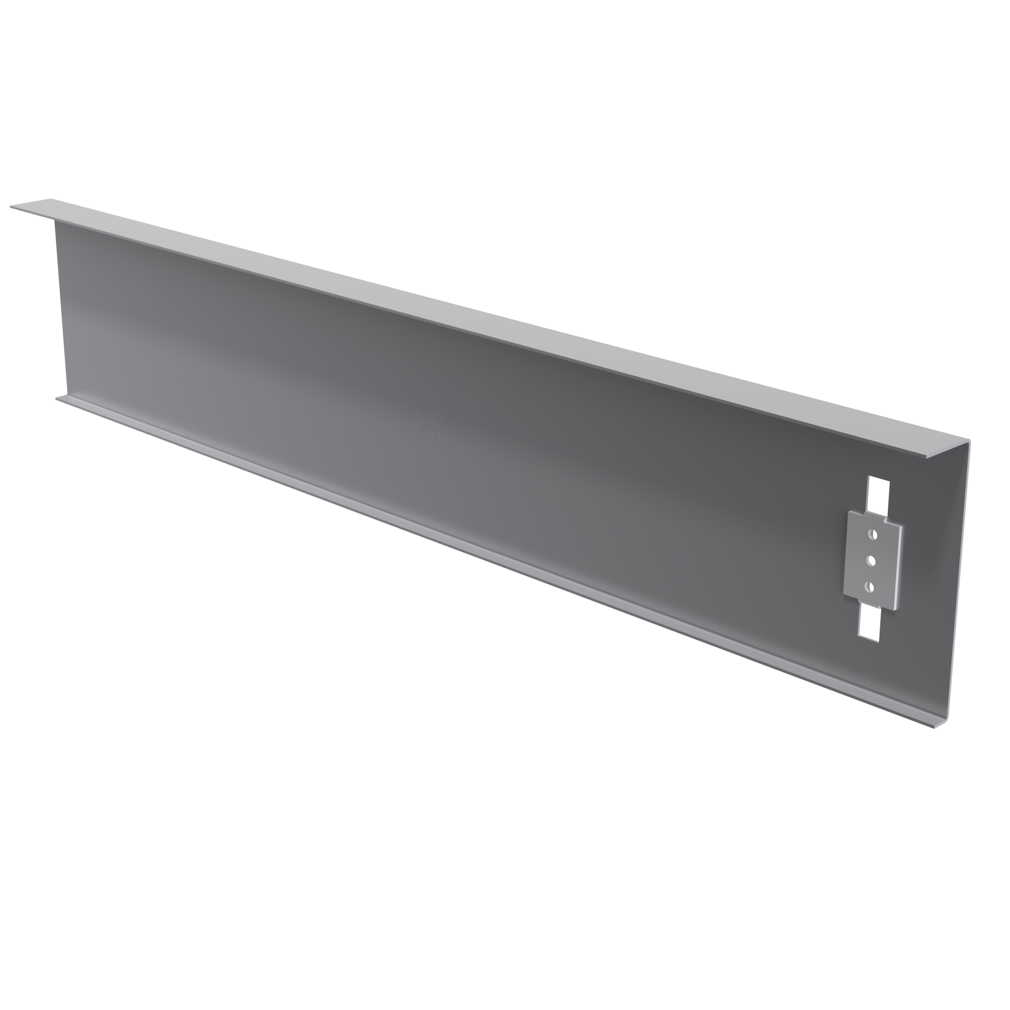
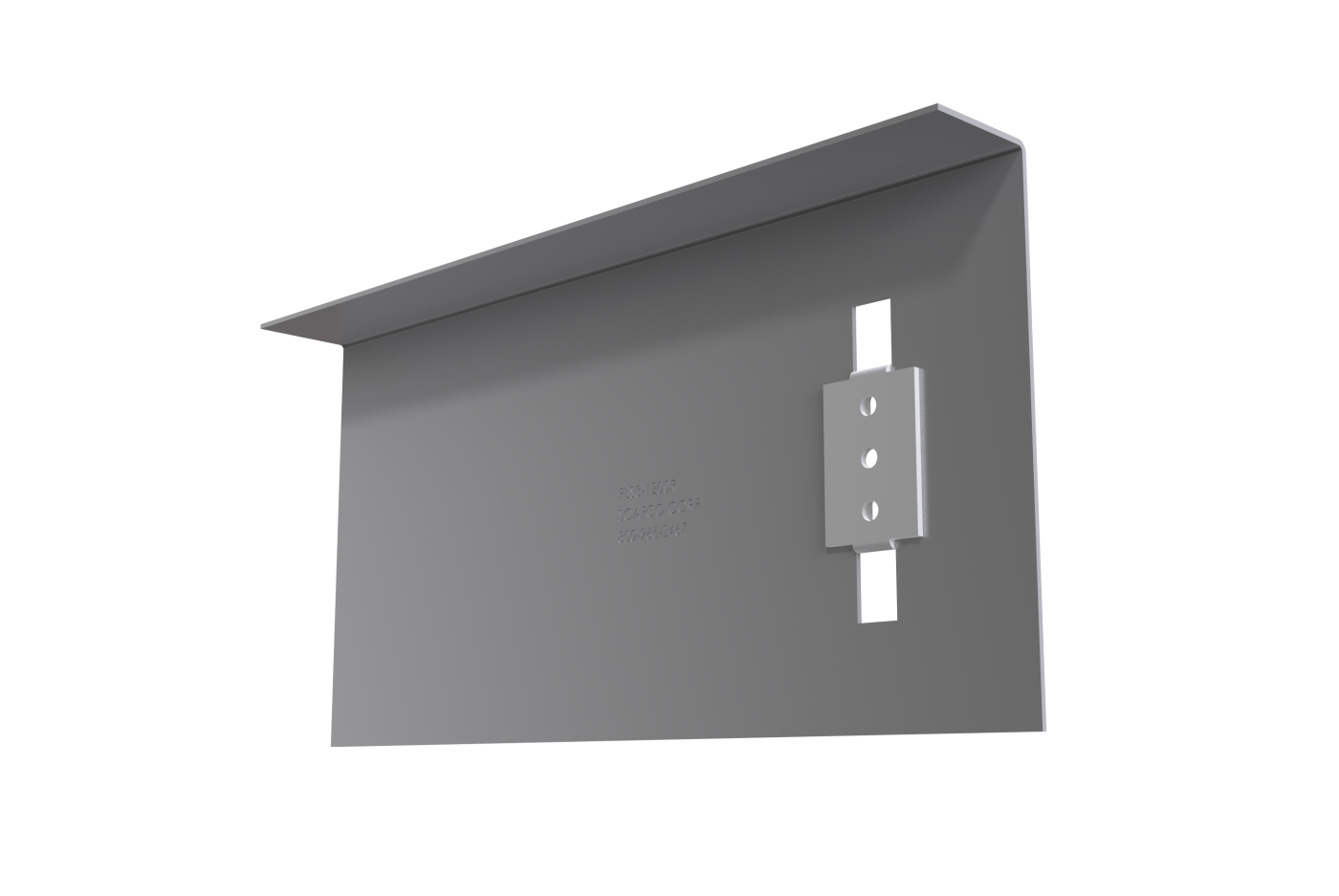
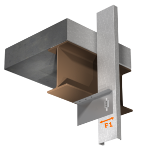
The PLS3 bypass slab slide strut attaches the bypass curtain wall stud to the building structure, allowing for vertical deflection while maintaining lateral rigidity. The strut provides a non-frictional connection and prevents vertical load transfer into the curtain wall. The insert is attached to the strut, making installation quick, easy, and efficient. Struts 12″ in length or less are packaged in durable buckets for convenient handling on the jobsite.
Features & Benefits
- Insert allows for 2” total vertical deflection
- Loads based on #12 screws
– Screws are provided - Large insert piece for easy installation
- Pre-punched guide holes
- Transfers horizontal load into structure
- Maintains lateral rigidity
- Eliminates bridging within 12” of support connection
PLS3 Submittal Download
Material Composition
- Mill certified steel
- ASTM A653/A653M
- Clip
– Material thickness: 68 mil
– Yield strength: 57 ksi
– Tensile strength: 65 ksi
– G90 galvanized coating - Insert
– Material thickness: 86 mil
– Yield strength: 57 ksi
– Tensile strength: 65 ksi
– G90 galvanized coating
Allowable Loads
| Part No. | Stud Thickness | F1 Allowable Loads (lbs) | ||||
|---|---|---|---|---|---|---|
| Mil | Gauge | Fy (ksi) | 2 #12 Screws | 3 #12 Screws | ||
| PLS3 | 33EQS | 20 | 57 | 462 | 692 | |
| 43EQS | 18 | 57 | 729 | 1093 | ||
| 33 | 20 | 33 | 377 | 565 | ||
| 43 | 18 | 33 | 561 | 841 | ||
| 54 | 16 | 50 | 1139 | 1709 | ||
| 68 | 14 | 50 | 1610 | 2180 | ||
| 97 | 12 | 50 | 2180 | 2180 | ||
| 118 | 10 | 50 | 2180 | 2180 | ||
| Maximum Allowable Clip Load | 2180 | 2180 | ||||
Table Notes
- Allowable loads have not been increased for wind, seismic, or other factors.
- The allowable loads are based on the steel properties of the members being connected, per AISI S100.
- The nominal strength of the screw must be at least 3.75 times the allowable loads.
- Penetration of screws through joined materials should not be less than three exposed threads. Install and tighten screws in accordance with the screw manufacturer’s recommendations.
- Screw shear capacities are based on allowable strength design (ASD) and include a safety factor of 3.0.
- Allowable loads indicated on the table(s) are for force in single direction only. The designer shall use the combined forces check as required by AISI S100 if more than one force is applied to the connection.
- The designer shall check the bending in the short leg of clip.
Quantity / Order Information
| Model No. | Left / Right Handed | Width | Qty / Bucket | Lbs / Bucket |
|---|---|---|---|---|
| PLS3-900 | (L) or (R) | 9″ | 35 | 49 |
| PLS3-1200 | (L) or (R) | 12″ | 30 | 55 |
| PLS3-1500 | (L) or (R) | 15″ | – | – |
| PLS3-1800 | (L) or (R) | 18″ | – | – |
| PLS3-2000 | (L) or (R) | 20″ | – | – |
All PLS3 clips include insert. Additional lengths available upon request.
Strengthening lip added for clips over 20″ lengths. See PLS3 illustration shown below with stiffening lip.