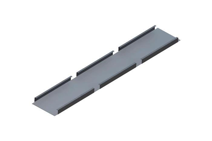
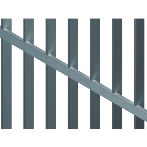
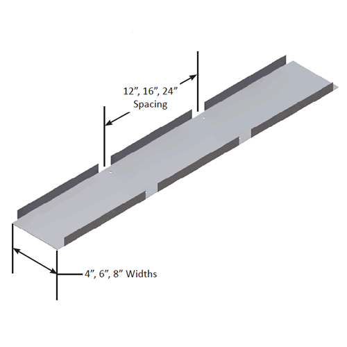
Notched Stud Backing (NS) is used for bracing and bridging of joists and wall studs in heavy load conditions. NS is also used in hospitals and schools as mechanical backing to provide superior support for equipment and cabinetry. Engineered section properties and allowable loads are provided based on 2004 AISI.
Features
- Pre-cut notches for flange attachment
- Pre-drilled guide holes
- Eliminates field cutting
- Provides bracing and bridging support
NS Submittal Download
Material Composition
- ASTM A653 / A653M
Yield Strength
- 30, 33, and 43 mil: 33 ksi
- 54, 68 mil: 57 ksi
Coating Thickness
- 30 mil: G40 hot-dipped galvanized coating
- 33, 43, 54 mil: G60 hot-dipped galvanized coating
- 68 mil: G90 hot-dipped galvanized coating
Material Thickness
- 30 mil
- 33 mil
- 43 mil
- 54 mil
- 68 mil
Nomenclature

Gallery
Section Properties
| 1/2″ Flange NS Section Properties – Per AISI Design Criteria | |||||||||
|---|---|---|---|---|---|---|---|---|---|
| Backing Member |
Thickness (mils) |
Thickness (ga) |
Depth (in) |
Flange (in) |
Fy (ksi) |
Ixe (min)(In4) | Sxe (min)(In3) | Iye (min)(In4) | Sye (min)(In3) |
| 4″, 33 mil | 33 | 20 | 4 | 0.50 | 33 | 0.386 | 0.193 | 0.007 | 0.018 |
| 4″, 43 mil | 43 | 18 | 4 | 0.50 | 33 | 0.495 | 0.248 | 0.008 | 0.022 |
| 4″, 54 mil | 54 | 16 | 4 | 0.50 | 50 | 0.603 | 0.301 | 0.009 | 0.025 |
| 4″, 68 mil | 68 | 14 | 4 | 0.50 | 50 | 0.728 | 0.364 | 0.011 | 0.029 |
| 6″, 33 mil | 33 | 20 | 6 | 0.50 | 33 | 1.085 | 0.357 | 0.007 | 0.018 |
| 6″, 43 mil | 43 | 18 | 6 | 0.50 | 33 | 1.416 | 0.472 | 0.009 | 0.022 |
| 6″, 54 mil | 54 | 16 | 6 | 0.50 | 50 | 1.736 | 0.579 | 0.010 | 0.026 |
| 6″, 68 mil | 68 | 14 | 6 | 0.50 | 50 | 2.116 | 0.705 | 0.012 | 0.030 |
| 8″, 33 mil | 33 | 20 | 8 | 0.50 | 33 | 2.214 | 0.526 | 0.007 | 0.018 |
| 8″, 43 mil | 43 | 18 | 8 | 0.50 | 33 | 2.989 | 0.738 | 0.009 | 0.022 |
| 8″, 54 mil | 54 | 16 | 8 | 0.50 | 50 | 3.727 | 0.932 | 0.011 | 0.026 |
| 8″, 68 mil | 68 | 14 | 8 | 0.50 | 50 | 4.569 | 1.142 | 0.012 | 0.030 |
| 1″ Flange NS Section Properties – Per AISI Design Criteria | |||||||||
|---|---|---|---|---|---|---|---|---|---|
| Backing Member |
Thickness (mils) |
Thickness (ga) |
Depth (in) |
Flange (in) |
Fy (ksi) |
Ixe (min)(in4) | Sxe (min)(in3) | Iye (min)(in4) | Sye (min)(in3) |
| 4″, 33 mil | 33 | 20 | 4 | 1.00 | 33 | 0.522 | 0.261 | 0.033 | 0.046 |
| 4″, 43 mil | 43 | 18 | 4 | 1.00 | 33 | 0.672 | 0.336 | 0.041 | 0.058 |
| 4″, 54 mil | 54 | 16 | 4 | 1.00 | 50 | 0.823 | 0.411 | 0.050 | 0.070 |
| 4″, 68 mil | 68 | 14 | 4 | 1.00 | 50 | 1.003 | 0.501 | 0.059 | 0.082 |
| 6″, 33 mil | 33 | 20 | 6 | 1.00 | 33 | 1.371 | 0.445 | 0.036 | 0.047 |
| 6″, 43 mil | 43 | 18 | 6 | 1.00 | 33 | 1.816 | 0.605 | 0.046 | 0.060 |
| 6″, 54 mil | 54 | 16 | 6 | 1.00 | 50 | 2.236 | 0.745 | 0.056 | 0.072 |
| 6″, 68 mil | 68 | 14 | 6 | 1.00 | 50 | 2.742 | 0.914 | 0.066 | 0.085 |
| 8″, 33 mil | 33 | 20 | 8 | 1.00 | 33 | 2.687 | 0.626 | 0.037 | 0.047 |
| 8″, 43 mil | 43 | 18 | 8 | 1.00 | 33 | 3.610 | 0.872 | 0.048 | 0.060 |
| 8″, 54 mil | 54 | 16 | 8 | 1.00 | 50 | 4.492 | 1.092 | 0.058 | 0.072 |
| 8″, 68 mil | 68 | 14 | 8 | 1.00 | 50 | 5.690 | 1.423 | 0.070 | 0.086 |
Allowable Loads
| Part No. | Stud Properties | Mx (lb*ft) |
Vy (lb) |
Pmax (lb) |
#10 Screw (lb) |
# Of Screw Required for Pmax |
||
|---|---|---|---|---|---|---|---|---|
| Mil | Gauge | Fy (ksi) | ||||||
| 400NS050-*-S??-33 | 33 | 20 | 33 | 257 | 976 | 308 | 177 | 2 |
| 400NS050-*-S??-43 | 43 | 18 | 33 | 379 | 1739 | 455 | 263 | 2 |
| 400NS050-*-S??-54 | 54 | 16 | 50 | 495 | 3372 | 594 | 500 | 2 |
| 400NS050-*-S??-68 | 68 | 14 | 50 | 593 | 4871 | 712 | 500 | 2 |
| 600NS050-*-S??-33 | 33 | 20 | 33 | 406 | 638 | 487 | 177 | 3 |
| 600NS050-*-S??-43 | 43 | 18 | 33 | 557 | 1415 | 668 | 263 | 3 |
| 600NS050-*-S??-54 | 54 | 16 | 50 | 767 | 2822 | 920 | 500 | 2 |
| 600NS050-*-S??-68 | 68 | 14 | 50 | 901 | 5350 | 1081 | 500 | 3 |
| 800NS050-*-S??-33 | 33 | 20 | 33 | 540 | 474 | 474 | 177 | 3 |
| 800NS050-*-S??-43 | 43 | 18 | 33 | 752 | 1051 | 902 | 263 | 4 |
| 800NS050-*-S??-54 | 54 | 16 | 50 | 1008 | 2091 | 1210 | 500 | 3 |
| 800NS050-*-S??-68 | 68 | 14 | 50 | 1228 | 4220 | 1474 | 500 | 3 |
| 400NS100-*-S??-33 | 33 | 20 | 33 | 486 | 976 | 583 | 177 | 4 |
| 400NS100-*-S??-43 | 43 | 18 | 33 | 641 | 1739 | 769 | 263 | 3 |
| 400NS100-*-S??-54 | 54 | 16 | 50 | 1146 | 3372 | 1375 | 500 | 3 |
| 400NS100-*-S??-68 | 68 | 14 | 50 | 1432 | 4871 | 1718 | 500 | 4 |
| 600NS100-*-S??-33 | 33 | 20 | 33 | 683 | 638 | 638 | 177 | 4 |
| 600NS100-*-S??-43 | 43 | 18 | 33 | 939 | 1415 | 1127 | 263 | 5 |
| 600NS100-*-S??-54 | 54 | 16 | 50 | 1705 | 2822 | 2046 | 500 | 5 |
| 600NS100-*-S??-68 | 68 | 14 | 50 | 2183 | 5350 | 2620 | 500 | 6 |
| 800NS100-*-S??-331 | 33 | 20 | 33 | 944 | 474 | 474 | 177 | 3 |
| 800NS100-*-S??-43 | 43 | 18 | 33 | 1318 | 1051 | 1051 | 263 | 4 |
| 800NS100-*-S??-54 | 54 | 16 | 50 | 2375 | 2091 | 2091 | 500 | 5 |
| 800NS100-*-S??-68 | 68 | 14 | 50 | 3118 | 4220 | 3742 | 500 | 8 |
Table Notes
- Web-height to thickness ratio exceeds 200. Web stiffeners are required at all support points and concentrated loads.
- Maximum point load, Pmax, is determined based on the minimum of the shear capacity or the bending capacity of the blocking/Part No., or the number of screws with proper edge distance/spacing that may be installed. Load assumed to act at mid-span through centroid of Part No., based on a span of 24″. For stud spacing of 16″ oc, above tables may conservatively be used.
- Number of screws determined by dividing Pmax by capacity of #10 screw and rounding up. Screw manufacturer shall confirm that their screws meet the code allowable capacity indicated in the table.
- Screw capacity based on stud material with thickness and yields strength equal to the blocking/Part No. Minimum screw spacing and edge distance shall not be less than 3 times the nominal screw diameter (per SSMA). For #10 screw, 3 x d = 3 x 0. 190″ = 0.57″.
- The properties indicated in the table have been calculated using CFS version 5.0.2 (RSG Software Inc.)
- Tabulated values do not consider stud capacity. Studs designed by others.
- All calculations based on 2004 AISI.