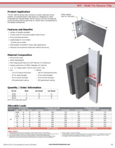
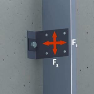
The wall tie secure clip (WT) connects a curtain wall stud to the exterior concrete/masonry wall structure through the use of a 90° angle. Secure clip (WT) is designed to resist horizontal and vertical loads. Pre-punched guide holes are provided in each leg, allowing for superior installation efficiency.
The secure clip (WT) may be attached to the structure with an approved ⅝” anchor bolt or as specified by the design professional.
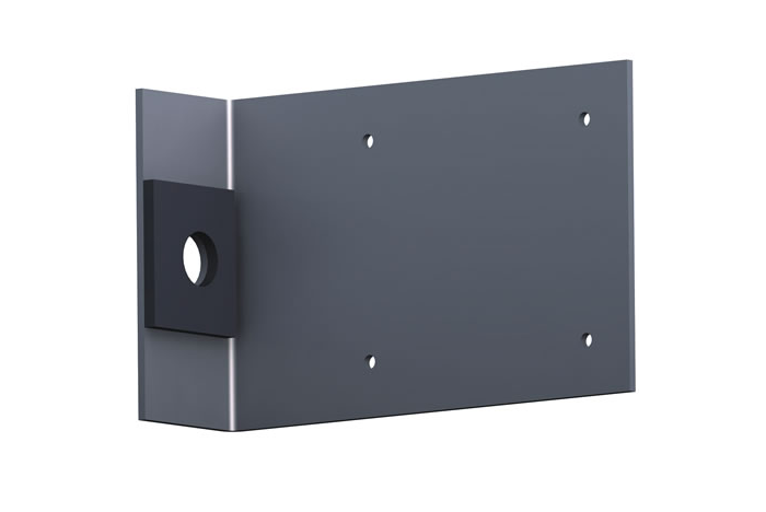
Features
- Provides pre-punched guide holes for quick attachment to structure and stud
- A variety of different lengths allowing for all requirements and construction tolerances
- Replaces the expensive traditional method of bracing
- Thicker steel for improving welded attachments
WT Submittal Download
Material Composition
- ASTM A653/A653M
- Yield strength: 57 ksi
- G90 hot dipped galvanized coating
- Clip material thickness = 114 mil
- Washer material thickness = 186 mil
Allowable Loads
| Model No. | Stud Thickness | Yield Strength (ksi) | Allowable Loads (lbs) | ||||||
|---|---|---|---|---|---|---|---|---|---|
| Mils | Gauge | F1 w/4 #10 Screws | F1 w/6 #10 Screws | F1 w/8 #10 Screws | F3 w/4 #10 Screws | F3 w/6 #10 Screws | F3 w/8 #10 Screws | ||
| WT | 33 | 20 | 33 | 708 | 1062 | 1416 | 708 | 1062 | 1416 |
| 43 | 18 | 33 | 1052 | 1578 | 2104 | 1052 | 1578 | 2104 | |
| 54 | 16 | 50 | 1480 | 2220 | 2960 | 1480 | 2220 | 2960 | |
| 68 | 14 | 50 | 2092 | 3138 | 4184 | 2092 | 3138 | 4184 | |
| 97 | 12 | 50 | 2092 | 3138 | 4184 | 2092 | 3138 | 4184 | |
Screw shear values are based on the SSMA Screw Table with the following notes:
- The allowable loads are based on the steel properties of the members being connected, per NASPEC with 2004 supplements.
- The nominal strength of the screw must be at least 3.75 times the allowable loads.
- Values include a 3.0 factor of safety.
- Penetration of screws through joined materials should not be less than 3 exposed threads. Screws should be installed and tightened in accordance with the screw manufacturer’s recommendations.
- Allowable loads indicated on the table(s) are for force in single direction only. If more than one force is applied to the connection, the designer shall provide the combined forces check as required by NASPEC with 2004 supplements.
- It is the responsibility of the designer to check the bending in the short leg of this clip.